last update: January 15, 2009.
This is an intermediate dsPIC project.
It interfaces a miniature C328 serial JPEG camera:
- image preview can be shown on an RGB OLED.
- captured JPEG images may be written to a MMC or SD card.
- camera connects @28.8 kbps.
- 2..10 images/min transfer, depending on resolution.
- User menu control via RS232/joystick. See details below.
- 7 user selectable operation modes:
- mode 1: 160x120 8-bit greyscale uncompressed to OLED.
- mode 2: (default mode) 160x120 16-bit (565) RGB uncompressed to OLED.
- mode 3: 640x480 JPEG YCbCr 4:2:2 compressed to RS232 (terminal screen.)
- mode 4: 640x480 JPEG YCbCr 4:2:2 compressed stored to SD card.
- mode 5: Four sequencial 80x60 8-bit greyscale previews: Quad-split OLED
- mode 6: 160x120 8-bit greyscale preview.
- mode 7: module and interface are both idle.
- Assembled and programmed pcb.
- Battery supply +3V5 ... +6V, integrated voltage regulator.
- ON/OFF with single pushbutton.
- Bootloader support.
- Hardware is compatible with other omniboard projects and can be upgraded.
- RGB 160x128 OLED and serial camera to be bought separately
Shop:
- KIT2: PCB + dsPIC + MMC/SD socket (programmed and assembled)
-
RGB OLED 160x128 Densitron DD-160128FC-2A
- Project box
- Complete source code (ccs compiler pcwhd)
KIT2 + OLED + JPEG Camera
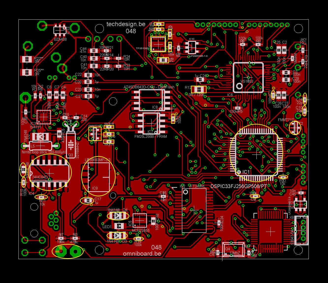
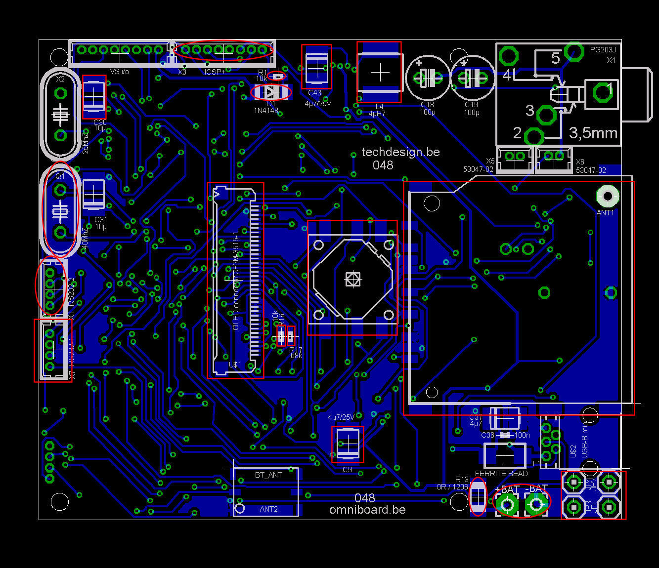
- Schematics: html, pdf, eagle
- PCB diagrams: html
- Partlist: html
- Software: KIT2 example: hex, c code oled, c code c328
- Bootloader: dsPICprogrammer, dsPICbootloader.hex, howto
- Complete source code (ccs compiler pcwhd) can bought from the webshop.

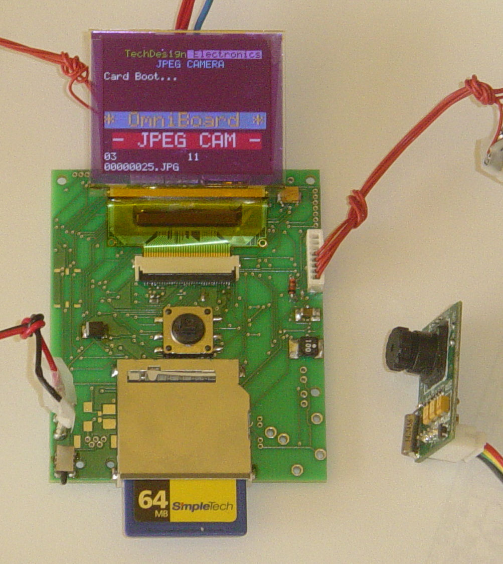
project example (053) with image preview to OLED
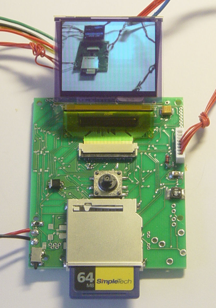
JPEG camera autoportrait, saved to SD card
How to make it work?
- Use a supply or battery between +3V5 ... +6V
- Optional terminal through RS232-1 @ 115200 bpS, 8N1, "type comm"
- JPEG camera connected via RS232-2
- MMC or SD(HC) cards must be formatted as FAT16. FAT32 will be supported later.
- Choose configuration via user menu:
- OLED preview: on/off
- save to MMC/SD(HC) card: on/off
RS232 terminal & bootloader.
- Tiny PIC bootloader for 16f and 18F chips.
- For dsPIC chips: our own modified command-line dsPICProgrammer: see omniboard bootloading.
- Or use the Windows 2000/XP terminal screen or third party terminal software.
- RS232 PIC <-> PC hardware interface: how to build it.
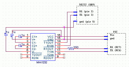
Omniboard ICSP+ (X3 connector) connection pins:
- !MCLR/VPP
- PGD (data)
- GND
- PGC (clock)
- +3v3
- leave open
- leave open
- leave open (closest to pcb corner)
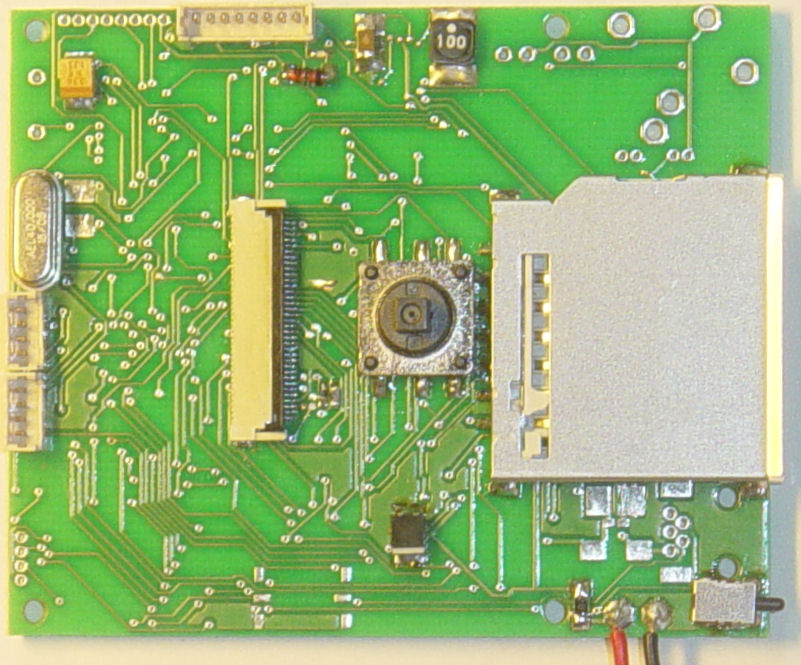
Images: (click images to view full resolution)
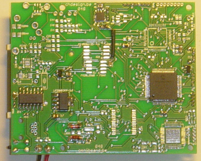
- dsPIC33FJ256GP506-I/L
- VReg LP38693MP-3.3
- Case Serpac M-6
- RGB OLED 160x128 Densitron DD-160128FC-2A
- Dc-up converter TPS61080
- 5-way joystick
Check out our development tools page.
Operation modes:
- mode 1: 160x120 8-bit greyscale uncompressed to OLED.
- mode 2: (default mode) 160x120 16-bit (565) RGB uncompressed to OLED.
- mode 3: 640x480 JPEG YCbCr 4:2:2 compressed to RS232 (terminal screen.)
- mode 4: 640x480 JPEG YCbCr 4:2:2 compressed stored to SD card.
- mode 5: Four sequencial 80x60 8-bit greyscale previews: Quad-split OLED
- mode 6: 160x120 8-bit greyscale preview.
- mode 7: module and interface are both idle.
User Menu: joystick controls:
- Enter (short): activates mode 1
- Right: mode 2
- Left: mode 3
- Up: mode 4
- Down: mode 5
- Enter (long): mode 7
User Menu: RS232 controls:
- Any number transmitted over the serial RS232 connection @ 115200 bps + ENTER.
- So 1...7 followed by ENTER (carriage return - 0x0d) activates the corresponding mode.
terminal screen output