last update: October 18, 2008
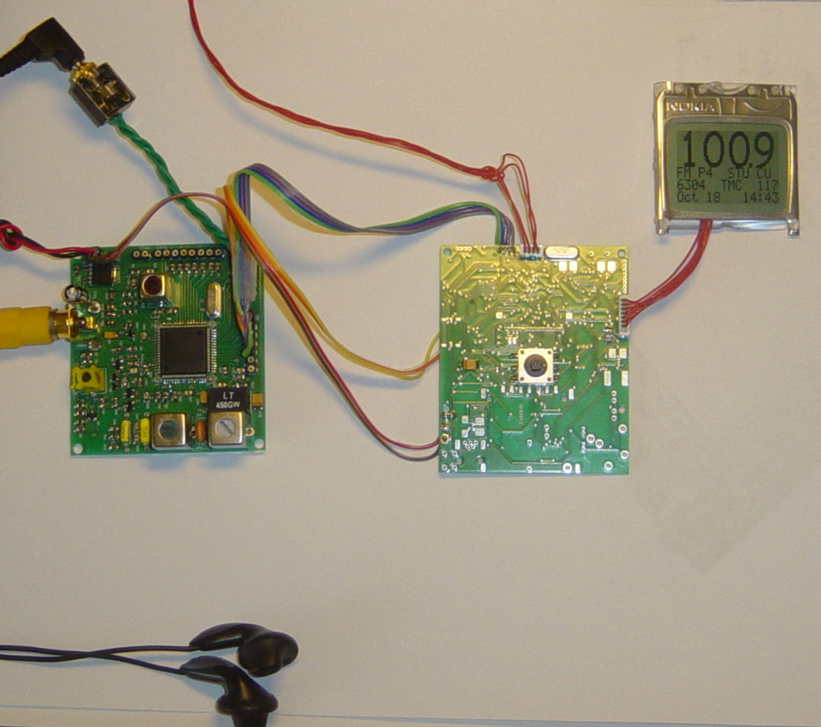
This is an intermediate dsPIC project which interfaces our Tuner Module and shows RDS station info and raw TMC (traffic message channel) messages. Display via serial RS232 or optional LCD.
-
User menu control via joystick:
- tune up/down
- station preset save/load
- volume up/down
- band change
- tuner calibration and auto preset
-
User control via terminal (RS232-2
serial com port:)
- tune up/down
- station preset save
- show current frequency
- tuner calibration and auto preset
- RDS info
available: (also see LCD readout and terminal printscreen below)
- PS (station name)
- PI, TA, TP (traffic program)
- CT (date and time)
- RT (radio text, rs232 only)
- raw TMC (rs232 only)
- Assembled and programmed pcb.
- Battery supply +9 ... +10V, integrated voltage regulator.
- Bootloader support.
- Hardware is compatible with other omniboard projects and can be upgraded.
Shop:
Tuner Module + KIT5 + LCD
Downloads:
- Schematics: gif, pdf, eagle
- PCB diagrams: html
- Partlist: html
- Software: KIT5 example: hex, c code TEF6901AH tuner chip
- Bootloader: dsPICprogrammer, dsPICbootloader.hex, howto
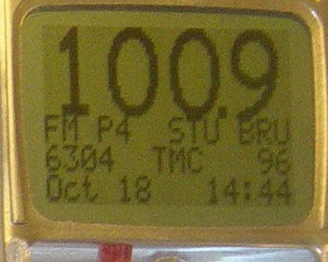
LCD readout
Images:
|
|
|
|
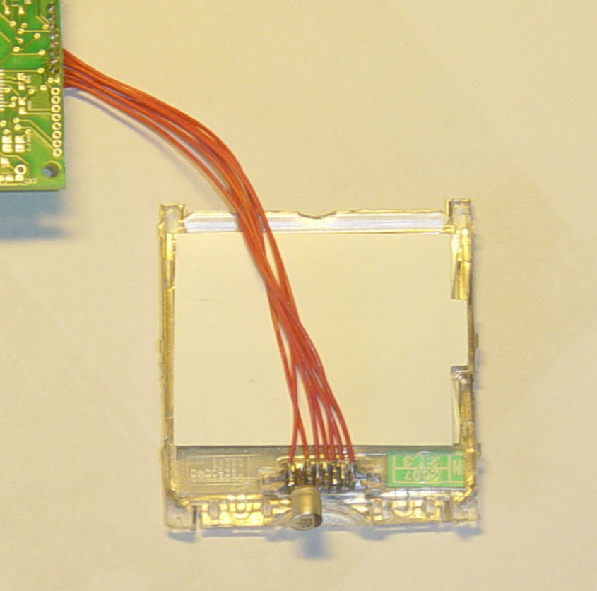
lcd backside detail |
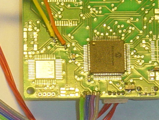
interface connection detail |
How to make it work?
- Use a single supply or battery between +9 ... +10V max. for both the tuner module and KIT5
- Optional terminal through RS232-2 @ 115200 bpS, 8N1, "type comm"
- Connect an antenna (a simple wire will do, length best at 1,20m but may be less)
- Control settings via user menu (micro joystick) or terminal:
-
User menu control via joystick:
- tune up/down (short right+left)
- station preset save/load (short enter/long right+left)
- volume up/down (short up+down)
- band change (long enter)
- tuner calibration and auto preset (hold right at boot)
-
User control via terminal
connection (RS232-2 to pc serial com port:)
- tune up/down (fru<CR> and frd<CR>)
- station preset save (sfr<CR>)
- show current frequency (gfr<CR>)
- tuner calibration and auto preset (ala<CR>, alb<cr> and ini<CR>)
How to connect the LCD?
| Omniboard ICSP+ (X3 connector) |
Nokia 3310 LCD pins |
|
|
5. +3v3 |
1. +3v3 | |
| 7. scl1 | 2. sclk | |
| 8. sda1 | 3. sda | |
| 2. pgd | 4. d/c | |
| 6. rb1 | 5. cs | |
| 3. gnd | 6. gnd | |
| (-) no connect | 7. vout (+0.47µF to ground) | |
| 4. pgc | 8. res | |
How to connect the tuner module to KIT5?
Omniboard pad Tuner Module I²C PIN_F6 (yellow wire) SCL (JP3-1) PIN_D9 (orange) SDA (JP3-2)
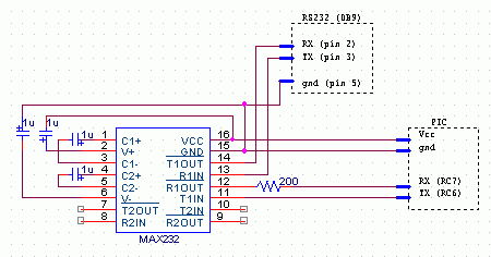
Omniboard RS232-1 Tuner Module RDS out 1. +3v3 (grey wire) + 3..5V µC (JP8) 2. U1TX (purple) RDCL (JP4-1) 4. U1RX (green) RDDA (JP4-2) Omniboard RS232-2 (X1 connector) connection pins:
- +3v3 (closest to T2 transistor "717")
- PIC TX
- GND
- PIC RX
RS232 terminal & bootloader.
- Tiny PIC bootloader for 16f and 18F chips.
- For dsPIC chips: our own modified command-line dsPICProgrammer: see omniboard bootloading.
- Or use the Windows 2000/XP terminal screen or third party terminal software.
- RS232 PIC <-> PC hardware interface: how to build it.
In case you need to reprogram the dsPIC from scratch, then use the ICSP+ connector X3, connected to a hardware programmer, like the dsPIC USB programmer: WinPic800.
Omniboard ICSP+ (X3 connector) connection pins:
- !MCLR/VPP
- PGD (data)
- GND
- PGC (clock)
- +3v3
- leave open
- leave open
- leave open (closest to pcb corner)
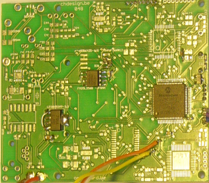
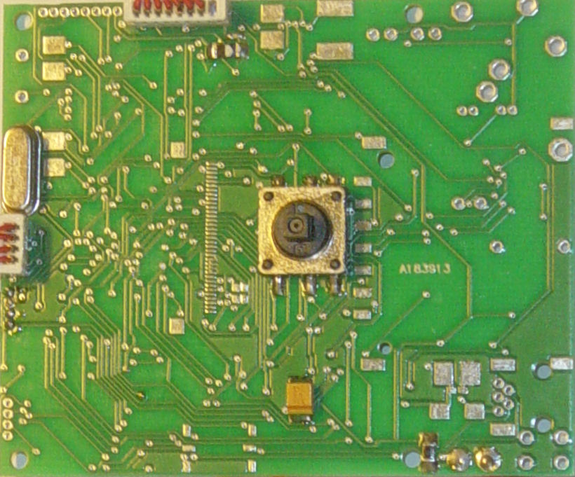
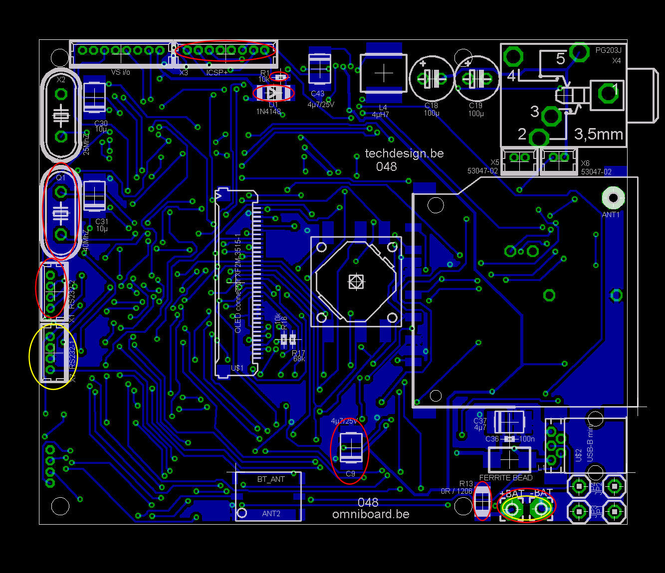
PCB Images: (click images to view full resolution)
Check out our development tools page.
terminal screen output